Page 1 of 2
[SOLVED] Desoldering motor wires caution
Posted: Sun May 19, 2013 9:07 pm
by kylejohnson
My latest crash landing resulted in a dented motor housing which prevents the rotor from spinning anymore.

No problem, I would just replace the motor with my spare. I proceeded to desolder the M3 connections using a wick and had an incredibly difficult time removing enough solder from the pads to reveal the hole where the wire would poke through.
I decided to flip the crazyflie over and carefully heated up the existing solder enough to pop the new motor wire in. That worked very well!
Though, my new motor does not spin. I seem to have been using the wick too much on the top side and may have removed a piece of a connector just under the first layer of the PCB? Using a multimeter, I find that my circle pad is connected through to the transistor, though the square pad does not connect through to the transistor. So, now I need to figure out where I can possibly use a patch wire to re-establish the square pad's destination.
My advice for motor replacement: don't de-solder from the PCB, just clip the old motor's wires and splice with the new motor's wires!
Disclaimer: I am a software guy with very little soldering experience.

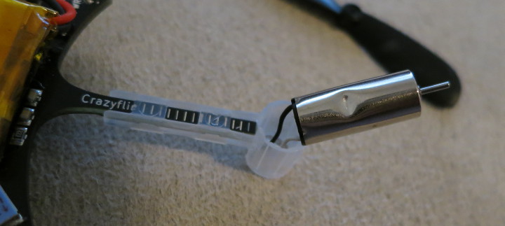
- dented motor
- dented_motor.JPG (43.17 KiB) Viewed 12346 times
Re: Desoldering motor wires caution
Posted: Sun May 19, 2013 9:42 pm
by atomicdog
The square pads goes to +BATT, so they shouldn't be tied to the transistor.
As you found out, it's easier to remove the wire first when there is still plenty of solder on the pad. I often add more solder to the tip of my iron before heating the pad, which makes it easier to remove parts. Once the wire is gone then removing the solder is easier. I also like to add flux to the wick so I don't have to rub the pad so hard to get the solder off.
Re: Desoldering motor wires caution
Posted: Sun May 19, 2013 10:58 pm
by kylejohnson
Thanks for the additional tips. One thing I've realized is that I have a ton of flux that is all over and around the motor pads. I should probably clean that off and reevaluate. The connections seem fine when I test with the multimeter. Maybe I just shorted out the new motor or something.
EDIT: I just tested the motors with a 1.5V AA battery and they function correctly. So, I'm back to debugging the PCB / soldering points.
Re: Desoldering motor wires caution
Posted: Sun May 19, 2013 11:50 pm
by atomicdog
Yeah, definitely clean of the flux. It's a magnet for solder blobs and metallic flakes. Plus it's easier to see if you have a good solder connection.
Re: Desoldering motor wires caution
Posted: Mon May 20, 2013 12:49 pm
by tobias
How's it going? Did you find the problem Kyle?
We are working on a improved motor mount to reduce the risk of denting the motor. Until then putting a stop/dampener between the PCB arm and the motor is a possible solution. Any ideas on what to use as stop/dampener? I was thinking about a piece of cut rubber band.
Re: Desoldering motor wires caution
Posted: Mon May 20, 2013 6:07 pm
by kylejohnson
Thanks for checking in! I have some rosin flux remover on mail order, so my next update will probably be next week. As for the next design of the motor mount, building a stop further away from the motor may be the best option. That, or just fabbing the mounts with harder plastic? Perhaps I can glue a stop in my existing mounts? The rubber band piece may also work well. I'll think about it some more.

tobias wrote:How's it going? Did you find the problem Kyle?
We are working on a improved motor mount to reduce the risk of denting the motor. Until then putting a stop/dampener between the PCB arm and the motor is a possible solution. Any ideas on what to use as stop/dampener? I was thinking about a piece of cut rubber band.
Re: Desoldering motor wires caution
Posted: Wed May 22, 2013 10:52 am
by Redouan
You can also lift the motor out of the mount en than cut the wires and than put a new motor and solder the wires to each other. It is better than desoldering on the PCB.It works for me!
Re: Desoldering motor wires caution
Posted: Sun May 26, 2013 8:36 am
by DonRex69
Hey Kyle!
Have you had any luck at debugging your soldering points or PCB yet? I'm having the same problem where I may have damaged the crazyflie whilst replacing a damaged motor! If you have repaired it could you put up a step-by-step guide?
Re: Desoldering motor wires caution
Posted: Thu May 30, 2013 2:14 am
by kylejohnson
Ok, my flux cleaner arrived and I cleaned the board. The cleaner really makes a difference in being able to see everything once again.

I can now tell that I didn't damage the board as horribly as I once thought.

My problem with M3 not spinning still remains, but I have solid multimeter readings to report to try to debug the issue and, hopefully, I can use a patch wire to correct the issue (which I have already attached). First, here is a photo of my board. You will notice that I obliterated the pads for M3 when I was originally using a soldering wick and trying to remove the solder from the hole in the pad. This damage was done before I figured out that I could easier pop the new motor wire through the reverse side, and is probably the source of my problem.
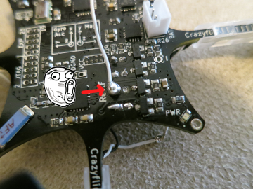
- original_board.png (182.95 KiB) Viewed 12193 times
When using a multimeter I miraculously find that the connections for the M3 wires are still working, except for one: square pad to transistor. I am hoping someone more knowledgeable could instruct me as to where I could connect a patch wire? Or otherwise help me figure out why square pad to transistor connection is not working? M3 Square pad to +BATT works and M3 Square pad to circle works, so some parts of the M3 square pad are ok ok. Here are my readings, with photos..
Square pad to BATT+ (M3 pad also successfully registers this value):
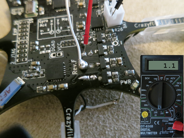
- measurement_square_battplus.png (181.92 KiB) Viewed 12193 times
Square pad to circle pad (M3 pad also successfully registers this value):
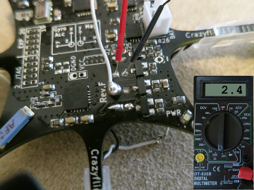
- measurement_square_circle.png (204.66 KiB) Viewed 12193 times
Square pad to transistor:
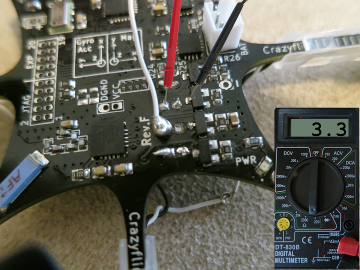
- measurement_square_transistor.png (204.78 KiB) Viewed 12193 times
M3 square pad to transistor (problem identified):
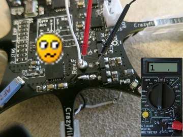
- measurement_m3_no_connection.png (181.67 KiB) Viewed 12193 times
Thanks for any help you can provide!
Re: Desoldering motor wires caution
Posted: Thu May 30, 2013 3:49 am
by kylejohnson
Here is a close-up of the M3 pads.. Underneath the blob of solder, the square M3 pad is in the same shape as the circle pad (it does not resemble a square pad anymore).

 No problem, I would just replace the motor with my spare. I proceeded to desolder the M3 connections using a wick and had an incredibly difficult time removing enough solder from the pads to reveal the hole where the wire would poke through.