I have just ordered my CrazyFlie and I to am interested already on what the chances of running a little bit bigger motor. I am going to look into it for sure.
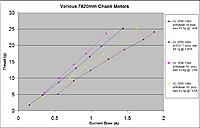
The power system itself can handle up to maybe 15W continuous (~1A per motor) but if too much power is drawn it tend to degrade the radio performance (then 2 Mbit mode tends to work better). We have successfully tried 7x16 motors but 7x20 motors should work as well. You should probably upgrade the battery when you do this as well.
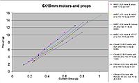
I have been looking more in detail into replacing the motors since i will be needing more power and a slightly larger frame and have narrowed it down to three choices:
There are some factors that limit the current.
1. The battery. The 170mAh battery for the Crazyflie has a protection circuit (PCM) to cut it off at over 4A continuous. Switch to a bigger and better battery.
2. The battery connector. Can be worked around by switching to a better connector or soldering the battery directly.
3. The board traces. These can probably handle 10A but has not been tested or calculated. External wires could be soldered to increase current capability.
4. MOSFETs. These should be able to handle at least 3A per motor.
5. The noise the increased current generate. This is probably the most difficult factor to handle but could be helped by putting decoupling capacitors between ground and the battery connected motor terminal.
Then there is the issue with the added weight, vibrations, etc which have to be taken care off.
So by taking care of the above you should be able to use the 8.5x20mm motors. Please let us know what you decide and how it turns out!
I will indeed get a bigger/better battery and probably replace the battery connector for the regular rc jst connector.
Do you have any more information on the trace width/copper thickness or any other way of calculating the max current of the traces? If not, i think i will have to go for the 7x20mm since the bigger 8.5x20 will draw around 11A max all together.
If im not wrong about the decoupling capacitors, they should be placed as close as possible to the motor on the + and - cables right?
Ill definitely post the progress of the project! I will start in the beginning of june but want to order the parts now so i have them by then!
It shouldn't be too hard to put an external +BAT wire. Or even easier, you can solder all positive motor wires directly to the battery connector (if they are long enough). Then that wont be an issue. Then you can also easily solder a capacitor, try maybe 100uF, between + and - on the battery connector.
The decoupling capacitor should be between +BAT and GND and not the + and - on the motor cables.