Hi, I am working my way through the plastic motor mount. Each time I have to unsolder and resolder the motor. I was considering reinforcing them but did not want to break other things as a result. Any ideas?
I seam to have a common failure where the bit that wraps around the PCB arm is pushed towards center and the motor is hanging off.
I don't understand why this happens. It seams logical the add a sleeve around the arm PCB so that this cannot happen. One end of the sleeve would be against the PCB at the inner end of the arm and the other against the begining of the plastic motor mount.
I have considered using heat shrink or perhaps a straw.
I also have some small polystirene balls that I was considering mounting on the bottom of the motors.
Anyone else tried to improve the motor mount, did it work or did you end up breaking something else.
Breaking motor mounts.
Re: Breaking motor mounts.
You don't happen to have a photo of a broken motor mount? I'm having a bit of trouble understanding where it breaks.
Ideally nothing would ever break") , but if it does it is good if the motor mount instead of the PCB arm since it is easier to repair/replace. I have not experienced any motor mount breaking easily though.
, but if it does it is good if the motor mount instead of the PCB arm since it is easier to repair/replace. I have not experienced any motor mount breaking easily though.
Ideally nothing would ever break
Re: Breaking motor mounts.
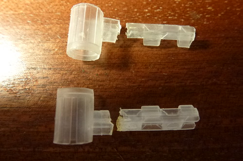
P1040664 by billybag2, on Flickr
As you can see I tried to glue one. A third has gone but is patched up on the flie at the moment.
So I think the failure mode is, looking at the top one, the arm is all the way in and touches the motor. The colision is usually on the bottom left of the motor and twists the motor sharply anti clock wise, (or should I day counter clock wise, one is international and the other is WTF are you talking about.)
This "cracks" (tares) the mount from the top down. The one on the flie is still attached at the bottom edge.
Re: Breaking motor mounts.
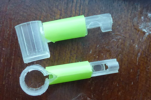
P1040665 by billybag2, on Flickr
This may help. Its a bit of straw with a small V to help thread the wire. Not glues it yet. Added 0.07gm for two mounts.
The main support will come from underneath. Glue to first and second "hump". This will provide stiffness and be under compression on impact.
Will try super glue as this will be light.
Re: Breaking motor mounts.
How would you rate the crashes that caused the motor mount to break? I will do some testing later tonight to see if I can replicate.
Don't make the motor mounts too strong though as the risk of breaking something else increases.
Don't make the motor mounts too strong though as the risk of breaking something else increases.
Re: Breaking motor mounts.
So I think they were power off dives from 1m-1.5m. Probably at an angle of 30 degrees pluss. Some were onto a hard floor (driveway). Onto carpet seams OK, I had one failure flying in the house but unsure what it crashed into, could of been some furniture.
I agree with the sentiment that I don't want the mounts renforced and then end up breaking the arms.
I have maybe not helped the issue by adding an auto cut at excesive angles. With zero thrust attitude control is completely gone. Perhaps crashing with some power on would mean a much flatter crash and alot less twist on the motors on impact. The props bashing against stuff is a horid noise but may actually be less damanging than a power off plumit.
Looking at the mount it looks and feels quite tough. There is, however, a statistically significant failure mode. But given the toughness based on inspection I think the forces to cause the failure must be large. If you can design out the force that would be great. But I think the force must be large so I think transfering the force somwhere else will just break something else.
I think you could reproduce conditiond with a spare board (bare may be enough), battery or dumy battery, four mounts and four motors. I think you need all the wieght to reproduce the forces. Then drop repeatedly onto a hard serface. I would be suprised if you are unable to reproduce the failure mode. Whether its worth doing something about is another matter.
(To be honest crash and burn for RC type stuff is common place. The faff is with removing and rewiring the motors. If this was easier then these breakages would be alot less of a pain.)
Re: Breaking motor mounts.
Thanks for you detailed analysis!
The motor mounts and PCB frame has been the most challenging thing to design and we are far from perfect. Before we had the moulded mounts we used 3D printed mounts which was much stiffer. They seldom broke but instead we had problems with that the electronics and the sensors broke. The PCB arms also broke more easily so in that sense the moulded softer mounts work better. As you point out having them break is not the issue but It should be easier to replace them, something we are working on. It is not trivial though as that involves adding connectors which somehow needs to be threaded through the mount or similar. With some clever design it should be doable...any ideas?
The motor mounts and PCB frame has been the most challenging thing to design and we are far from perfect. Before we had the moulded mounts we used 3D printed mounts which was much stiffer. They seldom broke but instead we had problems with that the electronics and the sensors broke. The PCB arms also broke more easily so in that sense the moulded softer mounts work better. As you point out having them break is not the issue but It should be easier to replace them, something we are working on. It is not trivial though as that involves adding connectors which somehow needs to be threaded through the mount or similar. With some clever design it should be doable...any ideas?
Re: Breaking motor mounts.
Agreed, don't make the mount so stong the PCB breaks.tobias wrote: It is not trivial though as that involves adding connectors which somehow needs to be threaded through the mount or similar. With some clever design it should be doable...any ideas?
I think the reality of my soldering is the wires are soldered to the pads. This is a combination of it being very dificult to remove solder from the hole and multi core wire never returns to a neat tinned end unless you trim it each time.
A suggestion would be increase the pad size and the clearance. First time you can still do a proper job. After a few repairs just tack the wire to the pad. This is not without its issues. You need the real estate and the ability to route to the seperated pads. I'm not sure if you can make a big pad on the underside and still keep the SM routing space on the component side. To maintain the through whole option you only need a small pad on the component side, but not as big as on the solder side.
You could provide alternative solder "tabs" so people can choose.
I cannot think of a better connector solution that would not add wieght. The battery connector is probably the best but I cannot see another four of these on the board. I'm quite happy to do the soldering but would like it require only veroboard/through hole standard of kit/skill. ie 0.1 pitch.
(If you consider any of this ramble you may want to consider adding the polarity swap to the PCB so all the wires are soldered the same way around for each motor. For example a row of white wires.)
Re: Breaking motor mounts.
Hi!
On the subject of replacing motor mounts, I've been having lots of trouble getting the cables through the PCB holes again. I've been looking of ways to desolder. This wikipedia page mentions 3 ways of removing the solder, using a vacuum pump, manual desoldering pump, or desoldering braid. Any advice on the different techniques? Or any recommended pumps?
On the subject of replacing motor mounts, I've been having lots of trouble getting the cables through the PCB holes again. I've been looking of ways to desolder. This wikipedia page mentions 3 ways of removing the solder, using a vacuum pump, manual desoldering pump, or desoldering braid. Any advice on the different techniques? Or any recommended pumps?
Re: Breaking motor mounts.
I actually don't remove the solder. I heat up the solder in the pad and remove the cable, then do the same when inserting. Adding some flux/new solder will help a lot and make the solder float nicely.