Hi Adiego,
welcome aboard
")
adiego73 wrote:
I'm not in a rush, but it would be awesome if you upload the camera holder model on
http://www.thingiverse.com/ or a similar site..
Ive uploaded the model to shapeways, where I ordered mine from:
Camera Holder. Ive ordered some more to double test that they work as advertised - they should arrive here in a week or two.
Note you will need the wide angle lens. I have some other (less developed models) that dont require the lens, but they are a little heavier. Or you just use a tiny bit of glue to keep the camera from shaking out
adiego73 wrote:
First of all, the receiver in FPV Hobby is out of stock, so I found this:
http://www.active-robots.com/shop-by-br ... odule.html Do you know if this receiver is similar to the one of your post? On the other hand, I've read that you were going to use a 2.4 GHz nano transmitter. Have you tried with one of those? Which one did you use?
I think the receiver you linked can do the same thing, but it does seem a little more sophisticated. FPVHobby seems to have the 5.8ers in
stock again. If you want to use the 5.8er transmitter I did, make sure that whatever receiver you buy supports one of these frequencies:
Ch1:5705mhz , Ch2:5685mhz , Ch3:5665mhz , Ch4:5645mhz , Ch5:5885mhz , Ch6:5905 , Ch7:5925mhz , Ch8:5945mhz.
A 2.4ghz receiver/
transmitter also exists. Ive had some bad experience with mine - not sure whats up with it, but others seem to be happy. Its lighter and smaller - you might want to look into that too. Browse these forums, some other people shared their results.
Good luck! And share your results with us
")
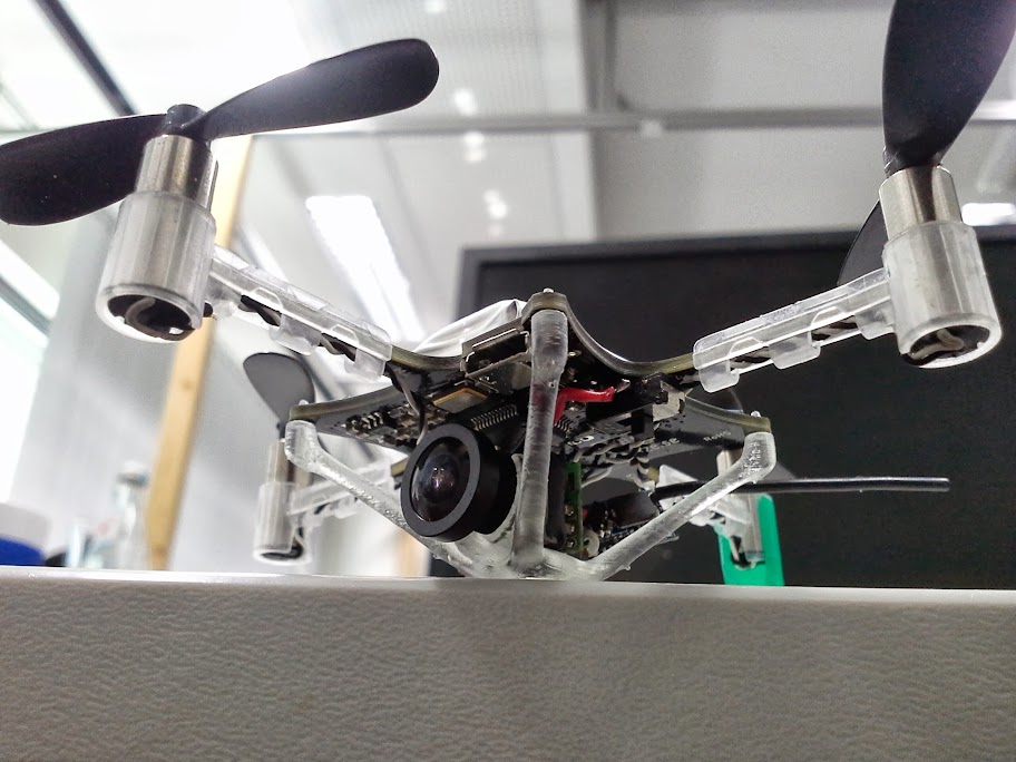
Here is a pic with the 2.4ghz transmitter and the model printed out using a form1 printer. Don't use a switch though, it could potentially cause a destructive LC votage spike.
Cheers
