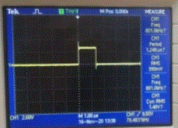
use ledring12.c file

Firmware/software/electronics/mechanics
Post Reply
SH_Lee
Member
Posts: 51
Joined: Tue Feb 18, 2020 8:48 am

use ledring12.c file

Post by SH_Lee »

I want to use the ws2812 led module.
I have already confirmed that the related functions are defined in the file called ledring12.
it is manipulated through Python files.

However, I would like to control the led by adding a new test without purchasing the ledring deck.
I'd like to know how to implement this.
What I've done now is as follows.
You tried to randomly select and execute one of the functions by adding the ledring12.h file to the new test.

Code: Select all

---
SYS: Crazyflie Bolt is up and running!
SYS: Build 73:a373c467177b (2020.09 +73) MODIFIED
SYS: I am 0x20373347344D500E0027003C and I have 1024KB of flash!
CFGBLK: v1, verification [OK]
Example task main function is running!DECK_CORE: 0 deck(s) found
IMU: BMI088 Gyro SPI connection [OK].
IMU: BMI088 Accel SPI connection [OK]
IMU: BMP388 I2C connection [OK]
ESTIMATOR: Using Complementary (1) estimator
CONTROLLER: Using PID (1) controller
MTR-DRV: Using brushless motor driver
EEPROM: I2C connection [OK].
STORAGE: Storage check [OK].
IMU: BMI088 gyro self-test [OK]
SYS: The system resumed after watchdog timeout [WARNING]
The following is the code I used.
1.example.c

Code: Select all

#include "config.h"
#include "debug.h"
#include "FreeRTOS.h"
#include "queue.h"
#include "static_mem.h"
#include "task.h"
#include "ledring12.h"
static xQueueHandle inputQueue;
STATIC_MEM_QUEUE_ALLOC(inputQueue, 1, sizeof(int));
static void exampleTask(void*);
STATIC_MEM_TASK_ALLOC(exampleTask, EXAMPLE_TASK_STACKSIZE);
static bool isInit = false;

#define white_led {0xff, 0xff, 0xff}
uint8_t led_buffer[][3] = {white_led,white_led,white_led,
							white_led,white_led,white_led,
							white_led,white_led,white_led,
							white_led,white_led,white_led};
//1st parameter

static bool led_test = true; //2nd parameter


void exampleTaskInit() {
  inputQueue = STATIC_MEM_QUEUE_CREATE(inputQueue);
  // TODO
  STATIC_MEM_TASK_CREATE(exampleTask, exampleTask, EXAMPLE_TASK_NAME, NULL, EXAMPLE_TASK_PRI);
  isInit = true;
}
bool exampleTaskTest() {
  return isInit;
}
void exampleTaskEnqueueInput(int value) {
  xQueueOverwrite(inputQueue, &value);
}


static void exampleTask(void* parameters) {
  DEBUG_PRINT("Example task main function is running!");
  while (true) {
    int input;
    exampleTaskEnqueueInput(input);
    if (pdTRUE == xQueueReceive(inputQueue, &input, portMAX_DELAY)) {
    	whiteSpinEffect(led_buffer, led_test);
      // Respond to input here!
    }
  }
}

2.ledring12.h

Code: Select all

#ifndef __LEDRING12_H__
#define __LEDRING12_H__

#include <stdint.h>
#include <stdbool.h>

#ifdef LED_RING_NBR_LEDS
#define NBR_LEDS  LED_RING_NBR_LEDS
#else
#define NBR_LEDS  12
#endif

#ifndef LEDRING_TIME_MEM_SIZE
#define LEDRING_TIME_MEM_SIZE 10
#endif

extern uint8_t ledringmem[NBR_LEDS * 2];

typedef struct __attribute__((packed)) timing
{
  uint8_t duration;       // How long this color should be show in parts of 1/25s. So 25 will show the color 1s, before going to the next color.
  uint8_t color[2];       // What color should be shown in RGB565 format.
  unsigned leds:4;        // What led should be show, 0 equals all leds.
  bool fade:1;            // Fade from previous colour to this colour during the full duration.
  unsigned rotate:3;      // Speed of the rotation, number of seconds per revolution
} ledtiming;

typedef struct timings
{
  uint32_t hash;          // Hash will later be used to check if the contents is already uploaded, so we don't reupload
  ledtiming timings[LEDRING_TIME_MEM_SIZE];
} ledtimings;

extern ledtimings ledringtimingsmem;

void whiteSpinEffect(uint8_t buffer[][3], bool reset);

#endif //__LEDRING12_H__


Q1 : How do I use the ledring12.c file on a bolt other than Python without using the ledring deck?
Q2 : Do you have any code that implements simple led ON-OFF?
Q3 : If you have a different c/h code than ledring12.c/h, could you share it?
kimberly
Bitcraze
Posts: 1050
Joined: Fri Jul 06, 2018 11:13 am

Re: use ledring12.c file

Post by kimberly »

Q1. The app layer: https://www.bitcraze.io/documentation/r ... app_layer/
Q2. Use the internal parameter api (https://github.com/bitcraze/crazyflie-f ... ram.c#L548). I guess you can use the ring.solidRed/Green/Blue but I guess you can try the parameters first out in the cfclient
Q3. There is a ledsequence api example in the app layer example folder: https://github.com/bitcraze/crazyflie-f ... pp_api/src Not sure if this is what you were looking for.

The example.c is still pre-app layer and meant for making your own deck driver, not necessarily to control another existing deck driver. To 'replace' python with something you can do onboard the crazyflie, that is exactly why we made the app layer for.
SH_Lee
Member
Posts: 51
Joined: Tue Feb 18, 2020 8:48 am

Re: use ledring12.c file

Post by SH_Lee »

I looked through the files you taught me.
But the file was a simple led on-off file.
The module I want to do is as shown in the following picture and is the same module as the leadring deck on your homepage.
11.GIF
11.GIF (20.02 KiB) Viewed 1800 times
aa1.GIF
aa1.GIF (28.09 KiB) Viewed 1800 times
The code we looked at to implement this is ledring12.c (crazyflie-firmware/src/deck/drivers/src/ledring12.c)
I want to control the files on the led tab on the client with the stored code.

The pins will use pb_5 (the same pins as the ledring-back pins)
The low pin cannot be used because only the matrix exists.(Why direct control without using the client's tabs)
SH_Lee
Member
Posts: 51
Joined: Tue Feb 18, 2020 8:48 am

Re: use ledring12.c file

Post by SH_Lee »

After I posted this article, I found a very simple way to do many experiments.
The function in the ws2812.c file was used without the code from the ledring deck.

And in the schema of the ledring deck, the power part is connected to the vcom, and I connected it to the vcc.
I don't know why, but the voltage/current doesn't seem to match the module I use.
I attached the code I used below.
When I tested various colors and brightness, I was very satisfied.

Code: Select all

#include "config.h"
#include "debug.h"
#include "FreeRTOS.h"
#include "queue.h"
#include "static_mem.h"
#include "task.h"
#include "ws2812.h"

static xQueueHandle inputQueue;
STATIC_MEM_QUEUE_ALLOC(inputQueue, 1, sizeof(int));
static void led_stripTask(void*);
STATIC_MEM_TASK_ALLOC(led_stripTask, LED_STRIP_TASK_STACKSIZE);

static bool isInit = false;
/*
static uint8_t led_buffer[12][3]={{0xff,0xff,0xff},{0xff,0xff,0xff},{0xff,0xff,0xff},
		{0xff,0xff,0xff},{0xff,0xff,0xff},{0xff,0xff,0xff},
		{0xff,0xff,0xff},{0xff,0xff,0xff},{0xff,0xff,0xff},
		{0xff,0xff,0xff},{0xff,0xff,0xff},{0xff,0xff,0xff}};
		*/
static uint8_t led_buffer[4][3] = {{0xff, 0x00, 0x00},{0xff, 0x00, 0x00},{0xff, 0x00, 0x00},{0xff, 0x00, 0x00}};

void led_stripTaskInit() {
  inputQueue = STATIC_MEM_QUEUE_CREATE(inputQueue);
  // TODO
  STATIC_MEM_TASK_CREATE(led_stripTask, led_stripTask, LED_STRIP_TASK_NAME, NULL, LED_STRIP_TASK_PRI);
  ws2812Init();
  isInit = true;
}
bool led_stripTaskTest() {
  return isInit;
}
void led_stripTaskEnqueueInput(int value) {
  xQueueOverwrite(inputQueue, &value);
}


static void led_stripTask(void* parameters) {
  DEBUG_PRINT("led_strip task main function is running!\n");
  while (true) {
    int input;
    led_stripTaskEnqueueInput(input);
    if (pdTRUE == xQueueReceive(inputQueue, &input, portMAX_DELAY)) {
    	DEBUG_PRINT("task is running!\n");
    	ws2812Send(led_buffer,4);
    	vTaskDelay ( M2T ( 2000 ));
    }
  }
}

color test (white/red)
a2.GIF

bright test(0x10 / 0xff)
a3.GIF
a3.GIF (33.42 KiB) Viewed 1798 times
aa1.GIF
aa1.GIF (24.6 KiB) Viewed 1798 times
SH_Lee
Member
Posts: 51
Joined: Tue Feb 18, 2020 8:48 am

Re: use ledring12.c file

Post by SH_Lee »

A new question occurred while using this to continue writing code.
We are experimenting with replacing the existing pb5 port with pb8.
Tim3 and Tim4 have not been further modified for the period because they have confirmed that they have the same performance on the datasheet.
And I changed the existing dma stream 5 to stream 7 and changed the time3_ch2 to tim4_ch3.
But the result was different from what I thought.
Is there anything else I need to know to succeed in this?
By default, timer channel, dma stream, dma channel, and dma interrupt number have been replaced only within the current code.

Q : What part of my code should I modify?

Code: Select all


#include <string.h>

// ST lib includes
#include "stm32fxxx.h"

#include "nvicconf.h"

#include "FreeRTOS.h"
#include "semphr.h"

//#define TIM1_CCR1_Address 0x40012C34	// physical memory address of Timer 3 CCR1 register

static TIM_TimeBaseInitTypeDef  TIM_TimeBaseStructure;
static TIM_OCInitTypeDef  TIM_OCInitStructure;
static GPIO_InitTypeDef GPIO_InitStructure;
static DMA_InitTypeDef DMA_InitStructure;
static NVIC_InitTypeDef NVIC_InitStructure;

static xSemaphoreHandle allLedDone = NULL;

// The minimum is to have 2 leds (1 per half buffer) in the buffer, this
// consume 42Bytes and will trigger the DMA interrupt at ~2KHz.
// Putting 2 there will divide by 2 the interrupt frequency but will also
// double the memory consumption (no free lunch ;-)
#define LED_PER_HALF 1

#define TIMING_ONE  75
#define TIMING_ZERO 29

static union {
    uint16_t buffer[2*LED_PER_HALF*24];
    struct {
      uint16_t begin[LED_PER_HALF*24];
      uint16_t end[LED_PER_HALF*24];
    } __attribute__((packed));
} led_dma;

void ws2812Init(void)
{
	uint16_t PrescalerValue;

  RCC_AHB1PeriphClockCmd(RCC_AHB1Periph_GPIOB, ENABLE);
  RCC_APB1PeriphClockCmd(RCC_APB1Periph_TIM4, ENABLE);
	/* GPIOB Configuration: TIM4 Channel 1 as alternate function push-pull */
  // Configure the GPIO PB4 for the timer output
  GPIO_InitStructure.GPIO_Mode = GPIO_Mode_AF;
  GPIO_InitStructure.GPIO_OType = GPIO_OType_PP;
  GPIO_InitStructure.GPIO_PuPd  = GPIO_PuPd_NOPULL;
  GPIO_InitStructure.GPIO_Speed = GPIO_Speed_25MHz;
  GPIO_InitStructure.GPIO_Pin = GPIO_Pin_8;
  GPIO_Init(GPIOB, &GPIO_InitStructure);


  //Map timer to alternate functions
  GPIO_PinAFConfig(GPIOB, GPIO_PinSource8, GPIO_AF_TIM4);

	/* Compute the prescaler value */
	PrescalerValue = 0;
	/* Time base configuration */
	TIM_TimeBaseStructure.TIM_Period = (105 - 1); // 800kHz
	TIM_TimeBaseStructure.TIM_Prescaler = PrescalerValue;
	TIM_TimeBaseStructure.TIM_ClockDivision = 0;
	TIM_TimeBaseStructure.TIM_CounterMode = TIM_CounterMode_Up;
    TIM_TimeBaseStructure.TIM_RepetitionCounter = 0;
	TIM_TimeBaseInit(TIM4, &TIM_TimeBaseStructure);

	/* PWM1 Mode configuration: Channel1 */
	TIM_OCInitStructure.TIM_OCMode = TIM_OCMode_PWM1;
    TIM_OCInitStructure.TIM_OutputState = TIM_OutputState_Enable;
	TIM_OCInitStructure.TIM_Pulse = 0;
	TIM_OCInitStructure.TIM_OCPolarity = TIM_OCPolarity_High;
	TIM_OC3Init(TIM4, &TIM_OCInitStructure);

//  TIM_Cmd(TIM4, ENABLE);                      // Go!!!
	TIM_OC3PreloadConfig(TIM4, TIM_OCPreload_Enable);
	TIM_CtrlPWMOutputs(TIM4, ENABLE);           // enable Timer 3

	/* configure DMA */
	/* DMA clock enable */
	RCC_AHB1PeriphClockCmd(RCC_AHB1Periph_DMA1, ENABLE);

	/* DMA1 Channel5 Config TM */
	DMA_DeInit(DMA1_Stream7);

	ASSERT_DMA_SAFE(led_dma.buffer);
  // USART TX DMA Channel Config
  DMA_InitStructure.DMA_PeripheralBaseAddr = (uint32_t)&TIM4->CCR3;
  DMA_InitStructure.DMA_Memory0BaseAddr = (uint32_t)led_dma.buffer;    // this is the buffer memory
  DMA_InitStructure.DMA_MemoryInc = DMA_MemoryInc_Enable;
  DMA_InitStructure.DMA_MemoryBurst = DMA_MemoryBurst_Single;
  DMA_InitStructure.DMA_MemoryDataSize = DMA_MemoryDataSize_HalfWord;
  DMA_InitStructure.DMA_BufferSize = 0;
  DMA_InitStructure.DMA_PeripheralInc = DMA_PeripheralInc_Disable;
  DMA_InitStructure.DMA_PeripheralDataSize = DMA_PeripheralDataSize_HalfWord;
  DMA_InitStructure.DMA_PeripheralBurst = DMA_PeripheralBurst_Single;
  DMA_InitStructure.DMA_DIR = DMA_DIR_MemoryToPeripheral;
  DMA_InitStructure.DMA_Mode = DMA_Mode_Circular;
  DMA_InitStructure.DMA_Priority = DMA_Priority_Medium;
  DMA_InitStructure.DMA_FIFOMode = DMA_FIFOMode_Disable;
  DMA_InitStructure.DMA_FIFOThreshold = DMA_FIFOThreshold_1QuarterFull ;
  DMA_InitStructure.DMA_Channel = DMA_Channel_2;
	DMA_Init(DMA1_Stream7, &DMA_InitStructure);

  NVIC_InitStructure.NVIC_IRQChannel = DMA1_Stream7_IRQn;
  NVIC_InitStructure.NVIC_IRQChannelPreemptionPriority = NVIC_LOW_PRI;
  NVIC_InitStructure.NVIC_IRQChannelSubPriority = 0;
  NVIC_InitStructure.NVIC_IRQChannelCmd = ENABLE;
  NVIC_Init(&NVIC_InitStructure);

  vSemaphoreCreateBinary(allLedDone);

  DMA_ITConfig(DMA1_Stream7, DMA_IT_TC, ENABLE);
  DMA_ITConfig(DMA1_Stream7, DMA_IT_HT, ENABLE);

	/* TIM4 CC2 DMA Request enable */
	TIM_DMACmd(TIM4, TIM_DMA_CC3, ENABLE);


}

static void fillLed(uint16_t *buffer, uint8_t *color)
{
    int i;

    for(i=0; i<8; i++) // GREEN data
	{
	    buffer[i] = ((color[1]<<i) & 0x0080) ? TIMING_ONE:TIMING_ZERO;
	}
	for(i=0; i<8; i++) // RED
	{
	    buffer[8+i] = ((color[0]<<i) & 0x0080) ? TIMING_ONE:TIMING_ZERO;
	}
	for(i=0; i<8; i++) // BLUE
	{
	    buffer[16+i] = ((color[2]<<i) & 0x0080) ? TIMING_ONE:TIMING_ZERO;
	}
}

static int current_led = 0;
static int total_led = 0;
static uint8_t (*color_led)[3] = NULL;

void ws2812Send(uint8_t (*color)[3], uint16_t len)
{
    int i;
	if(len<1) return;

	//Wait for previous transfer to be finished
	xSemaphoreTake(allLedDone, portMAX_DELAY);

	// Set interrupt context ...
	current_led = 0;
	total_led = len;
	color_led = color;

    for(i=0; (i<LED_PER_HALF) && (current_led<total_led+2); i++, current_led++) {
        if (current_led<total_led)
            fillLed(led_dma.begin+(24*i), color_led[current_led]);
        else
            bzero(led_dma.begin+(24*i), sizeof(led_dma.begin));
    }

    for(i=0; (i<LED_PER_HALF) && (current_led<total_led+2); i++, current_led++) {
        if (current_led<total_led)
            fillLed(led_dma.end+(24*i), color_led[current_led]);
        else
            bzero(led_dma.end+(24*i), sizeof(led_dma.end));
    }

	DMA1_Stream7->NDTR = sizeof(led_dma.buffer) / sizeof(led_dma.buffer[0]); // load number of bytes to be transferred
	DMA_Cmd(DMA1_Stream7, ENABLE); 			// enable DMA channel 2
	TIM_Cmd(TIM4, ENABLE);                      // Go!!!
}

void ws2812DmaIsr(void)
{
    portBASE_TYPE xHigherPriorityTaskWoken;
    uint16_t * buffer;
    int i;

    if (total_led == 0)
    {
      TIM_Cmd(TIM4, DISABLE);
    	DMA_Cmd(DMA1_Stream7, DISABLE);
    }

    if (DMA_GetITStatus(DMA1_Stream7, DMA_IT_HTIF7))
    {
      DMA_ClearITPendingBit(DMA1_Stream7, DMA_IT_HTIF7);
      buffer = led_dma.begin;
    }

    if (DMA_GetITStatus(DMA1_Stream7, DMA_IT_TCIF7))
    {
      DMA_ClearITPendingBit(DMA1_Stream7, DMA_IT_TCIF7);
      buffer = led_dma.end;
    }

    for(i=0; (i<LED_PER_HALF) && (current_led<total_led+2); i++, current_led++) {
      if (current_led<total_led)
          fillLed(buffer+(24*i), color_led[current_led]);
      else
          bzero(buffer+(24*i), sizeof(led_dma.end));
    }

    if (current_led >= total_led+2) {
      xSemaphoreGiveFromISR(allLedDone, &xHigherPriorityTaskWoken);

	    TIM_Cmd(TIM4, DISABLE); 					// disable Timer 3
	    DMA_Cmd(DMA1_Stream7, DISABLE); 			// disable DMA Stream7

	    total_led = 0;
    }
}

#ifndef USDDECK_USE_ALT_PINS_AND_SPI

void __attribute__((used)) DMA1_Stream7_IRQHandler(void)
{
  ws2812DmaIsr();
}
#endif

One suspicious part is 'DMA1_Stream7_IRQn'.
I didn't know exactly what function this was set.


---------------------------------------------------------------------------------------------------------------------------------------------------------------------


I conducted an additional experiment over the weekend.
Immediately after starting the cracyfly, we determined that the waveform and subsequent waveforms were different.
Before "Ready to fly" was output from the console of the client, the waveform was output normally and then the output changed.

1. before print "Ready to fly", same as normal code
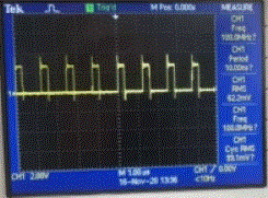
1.GIF
1.GIF (20.59 KiB) Viewed 1756 times
2. after print "Ready to fly"
2.GIF
2.GIF (21.06 KiB) Viewed 1756 times

Regardless of the existing code, the same waveform is output, but the changed code has identified the different house.
Therefore, I don't think it's a problem with rtos, and I doubt the possibility of changing the timer or dma setting in the middle.
In other words, I think this situation can occur by setting different settings for the timer or dma_stream that I want to write to in the middle of a different file.

1. I wrote the wrong code.
2. The code has no problem, but changes the setting for the corresponding timer (TIM4_CH3) or DAM_STREAM7 in another function or task.

Do you have any other ideas related to this?
tobias
Bitcraze
Posts: 2339
Joined: Mon Jan 28, 2013 7:17 pm
Location: Sweden

Re: use ledring12.c file

Post by tobias »

I think this is a resource collision problem because the TIM4 is used by the motor driver. Could you maybe use TIM3_CH1 on PB4 (IO_3) instead?
Attachments
Expansion deck pins.png
SH_Lee
Member
Posts: 51
Joined: Tue Feb 18, 2020 8:48 am

Re: use ledring12.c file

Post by SH_Lee »

I solved it after reading your article :D
I solved the problem, but I still have questions.
Each timer and channel is assigned to each dma stream and dma channel, which I understand is all independent.
Even if the timers are the same, if the channels are different, I think they are assigned to different dma streams and dma channels.
Therefore, I think there is no resource conflict.

If what I know is wrong, please correct it.
I would appreciate it very much if you could share your knowledge.
tobias
Bitcraze
Posts: 2339
Joined: Mon Jan 28, 2013 7:17 pm
Location: Sweden

Re: use ledring12.c file

Post by tobias »

I'm note 100% sure of this either but the timer setting is common for all channels so if you still have the same settings each channel is independent. However I think the motors and ws2812 requires different timer settings.
Post Reply